Oct
2008
Repairing the microphone of a Plantronics DSP-500 USB headset
A few years ago, I bought a DSP-500 USB/digital headset from Plantronics. It’s served me well with only some minor software glitches.
It has a swivel microphone on it that has obviously only just about stood the test of time. The swivel action took its toll on my headset, and other seem to suffer the same result as well. I set about fixing mine (or at least to see if I could fix it), to save me ordering an other headset. Here’s how to disassemble the headset (assuming you have a similar fault).
- First up, have your headset ready, along with a small Phillips screwdriver, and a small flat screwdriver (or a suitable plastic priser. Obviously, unplug the headset before starting repairs!
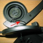
- Looking at the left earpiece (the one with the microphone), look in to the earpiece itself, and behind the foam, you’ll see where the earpiece being held by 4 clips (for the want of a better term). Prise the outer plastic away from the inner bulk of plastic at those 4 points (approximate positions arrowed in the picture below). That should release the inner plastic which forms the bulk of the earpiece.
- With the earpiece assembly released, a silver screw is exposed (arrowed in the image below) at the centre. Unscrew that to release the microphone assembly from the outside of the headset.
- Once disassembled, take care not to stretch the wiring (on either side of the headset assembly)
- Hopefully, you’ll see the damaged wire in roughly the same position (as this is where it’s usually kinked by the rotation of the microphone. It may be broken altogether. When working with this wire (a think co-axial wire), there are two things to keep in mind. First is that the wire is very thin and delicate, so treat it with care when stripping it. Secondly is that the outer and inner cores aren’t all that conductive (presumably because the mix of copper and other materials used) so when you’re using a standard multimeter, for example, it might not work like you expect.
- Carefully strip back the outer (black) insulation, and the inner (white) insulation. Repair, by soldering at least a few millimetres of the copper portion of each core. Be careful to adequately insulate the cores from each other. Luckily, there’s a bit of spare length in that wire to work with.
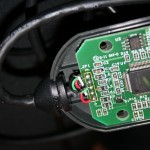
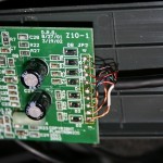
Update: As requested (quite some time ago!), I’ve added photos of the wiring in the sound-card circuit-board (that bulky Plantronics-branded box that’s inline, just above the USB plug. The wire colours are listed below, and are top-down as you’re looking at the circuit board with the printed text the right way up (i.e. “Copyright Plantronics” is down the bottom-left of the board).
For the left hand side of the circuit board (that’s the side with the USB plug), the order is bare (no colour cover), black, green, white and red. For the right side (the headset side), it’s: green, blue & copper/bare, red, green & red, blue, green & copper/bare, red & copper/bare, copper/bare (no colour), and white.
Click on the images (and then click the image on that page, again!) to see larger versions:
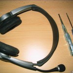
- Step 1: The Plantronics DSP-500 Headset
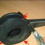
- Step 2: Unclip the earpiece assembly
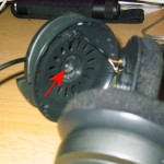
- Step 3: The exposed inner screw of the earpiece
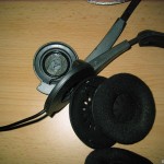
- Step 4: The earpiece assembly dissassembled
- Step 5: The damaged wire exposed
- Extra: USB plug, left-hand, side of DSP-500 circuit board
- Extra: Headset, right-hand, side of DSP-500 circuit board
15 Responses:
Leave a Reply
You can follow any responses to this entry through the RSS 2.0 feed. You can leave a response, or trackback from your own site.

Search
Categories
Links
Tags: 


Thanks,
Saved me some time finding how to disassemble!
Exactly the same fault with the broken microphone wire.
The core of the cable does indeed contain plastic threads and also the wire seems to be coated like enamelled copper wire. However this melts off during soldering.
Thanks.
Martin
thanks for the pictures my mic stopped working and I was able to follow your directions to check my wiring. I’ve been using these headphones for 5 years or more now and they still work great. I tripped over them earlier tonight and the mic stopped working. I was able to find that some wires pulled loose in the sound card but am unable to find a wiring diagram for them. I was wondering if you happen to have any pictures of that part of the device. If you do and could email them to me I would greatly appreciate it. I have been unsuccessful finding anything online.
thanks
Kenneth
i have an even older pair of basically the same model w/ the exact same problem, cant solder it yet but this info is gonna make fixing the mic alot easier thanks for the post
Hey, thanks for posting this. I was about to destroy the headphones by trying to enter from the wrong side until i saw your post explaining where the clips were.
Kenneth, I don’t have easy access to the sound-card bit of the headphones, I’m afraid. I’ve been meaning to grab a photo since you commented, but haven’t had the time to dig it out (it’s tucked away with about 100 wire ties).
I have opened it, twice now, to repair it having pulled the wire loose like you. I didn’t have to solder it (there’s a sticky black tape over the soldering that was good enough in my case). I hadn’t pulled the wire completely loose (just 2 of the cores had disconnected), and it was obvious where they went back. I’ll try a get a photo up soon, but it won’t be this week, I’m afraid.
maaan thanks, i been tryin to disassemble my dsp500 but didnt find any visible screws or anythin)) so clips, huh?)) thanks a lot
I have the same problem as cgarvey. I opened the piece and there were three wires stuck out. There are a total of 9 wires altogether. Now i dont know which wire belongs to which circuit. Can somebody help me out on this? A good photo would do, i guess
Normally, I’d quip “ask, and thou shall receive” but I noticed I’d already promised a photo over a year ago. Humble apologies, and I’ll get on that right away.
As promised, photos and pinouts of the sound-card circuit board. Apologies for the delay! Pay attention to the order of colour listings above (top-down as you’re looking at the circuit board with the text the right way up).
You’ll need a good, bright, white light to be able to distinguis the colours of the headset wiring!
I have successfully repaired my Plantronics Gamecom Pro1 after reading your post.
Thanks a lot!
sorry my eng its bad. Gracias por el tutorial y las fotos la verdad la configuracion jamas la hubiera podido repararlas. gracias de nuevo.
De nada!
Gamecom Pro = DSP500 rebranded, for those of you who don’t know.
Thanks for the post, repaired my age-old headset with the pics…needed fix the wire going from sound card to L earpiece, but the damaged wire was inside the earpiece. Splice & Dice!
Thanks a lot! I had a problem with my mic and left earpiece, but with your help i have disassembled it and fixed that screw. DSP-500 rules.
Thanks, this helped me fix my Gamecom Pro’s bad right speaker. I don’t know if I would have figured out that the foam ear pieces popped out without damaging them were it not for this. I had a break in the red wire somewhere near the left speaker so I cut a few inches off and resoldered all 5 wires back to the circuit board inside the left ear. It’s great to have my favorite headset back.